|

Please read this manual carefully before using this product. If you have any questions, please consult relevant professionals or contact us directly.
Summary
External dimension: 143x34x110mm, mounting position: 5mm
High performance processor is adopted to improve data processing speed and control reliability
It is convenient to fit all kinds of electronic hysteresis devices
Display accuracy: 1g
The voltage adjustment accuracy is 0.01 times
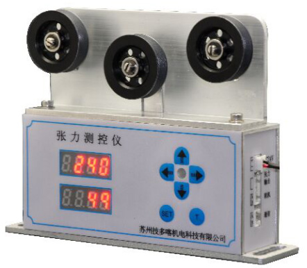
The CKY series tension controller is widely used in motor rotor, transformer, coil and other winding machines
Product description
1、Model introduction
CKY series tension controller and our integrated tension control frame consist of the following models
|
model |
Applicable tension (g) |
Reference wire diameter(mm) |
|
CKY-W-1 |
0-5000 |
0.05-1.0 |
|
CKY-W-2 |
0-5000 |
0.05-1.0 |
|
CKY-W-3 |
0-5000 |
0.05-1.0 |
|
CKY-W-1-LL |
0-20000 |
2.0-3.0 |
2、Model Description: the above products are divided into right side model and left side model.
Cky-w-1: w (tension display) - 1 (anti jump guide wheel), l plate (length 160), ll plate (length 200)
Cky-w-2: w (tension display) - 2 (aluminum guide wheel - installation position 30 degrees)
Cky-w-3: w (tension display) - 3 (aluminum guide wheel - installation position 10 degrees)
Customers can choose the right model according to their machine position.
3、Description of main technical parameters
Power supply: DC24 V ± 1 V
Power consumption: ≤ 4W
Output signal: voltage 0-23.5v, current 0-0.6a
Use environment: temperature 0-50 ℃, humidity ≤ 85%
Storage temperature: room temperature
4、Panel description
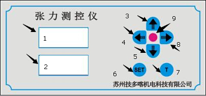
Introduction to front panel
 
Introduction to front panel operation:
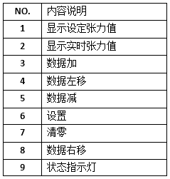
1. Under the initial interface. In the figure above, position 1 shows the set tension, and position 2 shows the real-time tension. At this time, you can do the following:
A: Short press the "set" button. Enter the interface of "setting upper and lower limit of tension", the red light will be on to set the upper limit of tension value, and the white light will be on to set the lower limit of tension value.
B: Long press the "t" button. Carry out clearing operation. The sign of successful reset operation is that the status indicator flashes once.
2. Set the tension interface. At this time, you can do the following:
A: Data adjustment
In the set tension interface. The corresponding adjustment bit will flash continuously. The adjustment bit can be selected by "shift left" (key 4) or "shift right" (key 8).
After selecting the adjustment bit, you can adjust the data by "data plus" (key 3) or "data minus" (key 5).
B: Short press the "set" button. Enter the "set upper and lower limit of tension setting" interface, the red light is on to set the upper limit of tension value, the white light is on to set the lower limit of tension value, when the tension is higher than the upper limit, the red light is always on, when the tension is lower than the lower limit, the white light is always on, and the light does not flash within the tension range.
The output voltage is directly proportional to the set value.
C: Short press the "set" button to exit the adjustment interface. The status indicator is off.
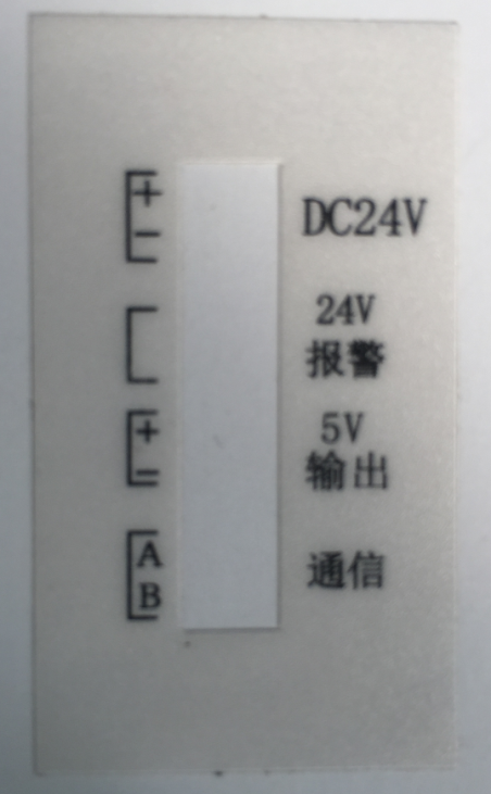
Introduction to side panel

The side port is the wiring port
The upper port is a 2-pin power interface: the top is the positive pole of the input power supply, and the bottom is the negative pole of the input power supply.
The middle port is a 4-pin socket: the upper two bits are the alarm output interface (DC24 V).
The following communication socket: computer connection socket. The computer needs to be equipped with USB to 485 communication module
|