Product Manual
First, model brief introduction
CKY series tension controller and the integration of the tension control frame composed of the following models
|
Model |
Applicable tension(g) |
Reference diameter(mm) |
|
CKY-AB-500 |
300-3000 |
0.22-0.80 |
|
CKY-AB-1000 |
800-5000 |
0.35-1.0 |
Second, the model description: The above products are divided into the right model and left model.
CKY-AB-500-R: AB (closed-loop control) -500 (3000 grams of hysteresis) -R (right model)
CKY-AB-500-L: AB (closed-loop control) -500 (3000 grams of hysteresis) -L (left model)
Customers can choose the right model according to the position of the machine.
Third, the main technical parameters
Power supply: DC24V ± 1V
Power consumption: ≤ 4W
Output signal: voltage 0-23.5V current 0 - 0.6A
Use of the environment: Temperature 0-50 ℃ Humidity ≤ 85%
Storage temperature: Store at room temperature
Fourth, the panel instructions
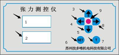
Front Panel Introduction


Front Panel Operation:
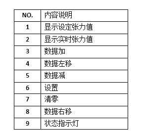
1. Initial interface. In the figure above, position 1 shows the set tension, position 2 shows the real-time tension. The actions that can be performed at this time are:
A: Short press "SET" button. The "Set tension" screen appears. In the tension setting interface, the status indicator lights up
B: long press "T" button. Perform a clear operation. The flag for the success of the clear operation flashes for the status indicator.
2. Set the tension interface. The actions that can be performed at this time are:
A: Data adjustment
The tension interface is set. The corresponding adjustment bit will flash continuously. The shift bit can be selected by "Shift Left" (key 4) or "Right shift" (key 8).
After selecting the adjustment bit, the data can be adjusted by "Data Plus" (key No. 3) or "Data subtraction" (key No. 5).
B: Short press "SET" button to enter the voltage adjustment interface. Voltage adjustment interface, the status indicator switch to red.
3. Voltage adjustment interface. At this point you can operate is:
A: Voltage adjustment
In the voltage adjustment interface. The default display is "21.00". "2" for the interface logo, can not be adjusted. The remaining three can be adjusted.
The corresponding adjustment bit will flash continuously. The shift bit can be selected by "Shift Left" (key 4) or "Right shift" (key 8).
After selecting the adjustment bit, the data can be adjusted by "Data Plus" (key No. 3) or "Data subtraction" (key No. 5).
Output voltage and set value is proportional to the relationship.
B: Short press "SET" button, exit the adjustment interface. The status indicator turns off.
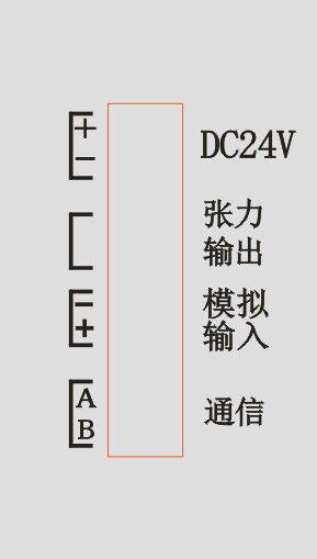
Introduction to the rear panel

The rear port is the wiring port:
The top port for the 2-pin power connector: the top for the input power of the cathode, the following is the negative input power.
The middle port for the 4-pin socket: the top two are the hysteresis interface. Regardless of positive and negative polarity
The following two for the online communication interface.
The following communication jacks: Computer connection (485) jack.


